


Yet another major part of the build that can probably be as simple or as complicated as one likes. I think I went for somewhere in between. For solar panel installation please see installing the solar panels
Update: In my book I go through and explain everything needed, in clear detail, for the vans electrical system (and a solar panel setup). I start with basic electronics so no one is left out. Get the ebook as an instant download here
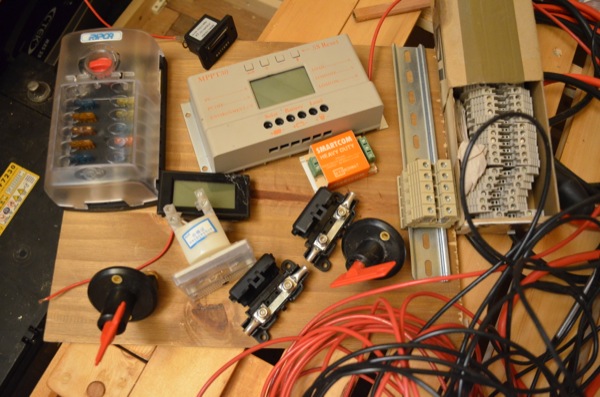
Here’s a list of the materials I used
| Item | Description | Cost | Quantity | Supplier |
| midi strip fuse holder | used for fusing each battery | £2.79 | 2 | Amazon(bargainbitz) |
| 12 way blade fuse box (RIPCA) | for main 12V power distribution | £20 | 1 | Ebay (2nd hand) |
| Battery isolator cut off switch | 100A switch often seen in marine and automotive applications | £5 | 2 | Amazon (radio world) |
| 2.5mm2 cable | I got 10m of red and 10m of black for general low power stuff such as lights and general hook up | £6.99 for 10m | 20m | Ebay (CCS-UK) |
| 10mm2 cable | 5m of red and 5m of black for utility terminals | £2.10 per metre | 10m | Auto electric supplies (AES) |
| 20mm2 cable | 4m red 4m black for wiring the solar controller up. | £3.60 per metre | 8m | Auto electric supplies (AES) |
| Analog panel meter ammmeter | 0 to 20A reading | £3.97 | 1 | Amazon (sourcingmap) |
| LCD digital volt panel Voltmeter | 7.5-20V | £4.39 | 1 | Amazon (lgking supply) |
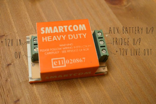
| Smartcom split charge relay | 30A voltage sensing relay with inline fuses and terminals (kit) | £17.00 | 1 | Ebay (Brocotts) |
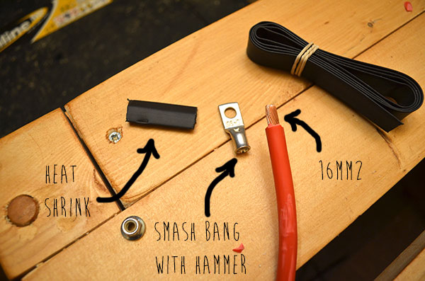
| heatshrink sleeving 4.8mm before heat | Used for cable terminals | £0.77 | 1 | Auto electric supplies (AES) |
| Assorted cable crimps | I already had most of these | – | – | – |
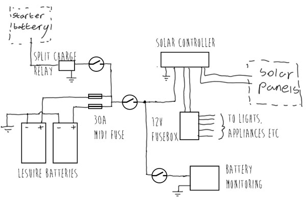
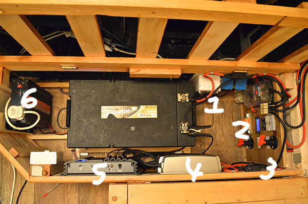
After I had a decent collection of wire and bits I started by scribbling a few sketches for how I thought the batteries should be connected, fused, isolated etc and then just made it up as I went along.
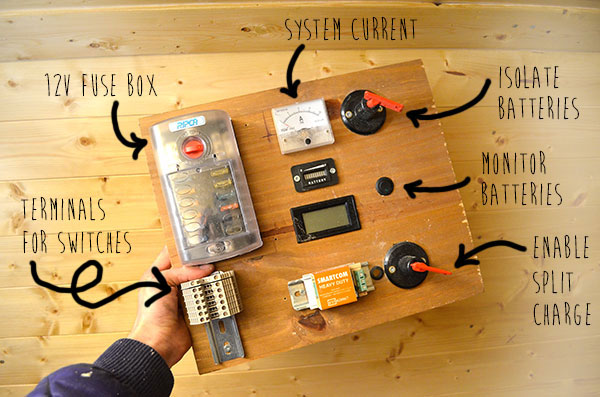
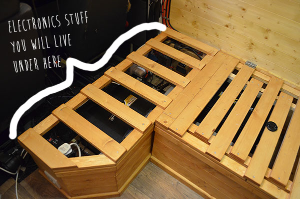
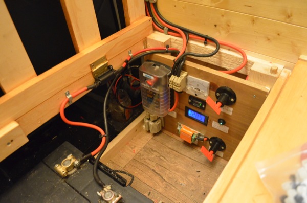
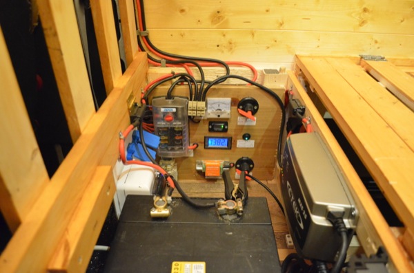
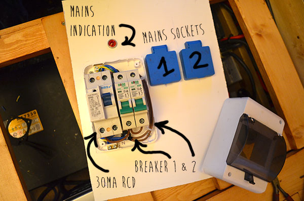
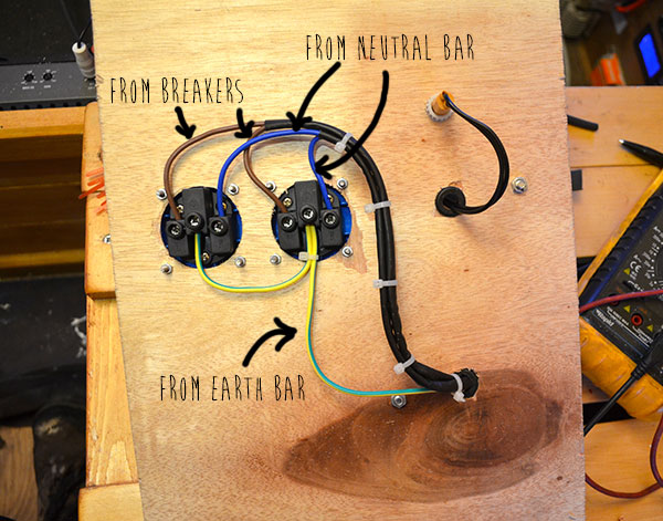
Assembling the 12V power distribution panel

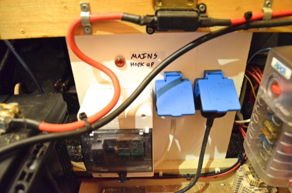
Mains hookup
The mains hookup will be used for when there is mains available – campsites, lamp posts etc. It will be used to power the CTEK charger which will charge the batteries and supply the normal 12V power.
So thats about it for the electric stuff, although it may be adapted, improved or even simplified as I start living in the van but its a start. Also I’m still yet to wire and test out this smartcom voltage sensing relay for split charging of the leisure batteries. I’ll report back on that one….
Split charging relay (Smartcom Voltage sensing)
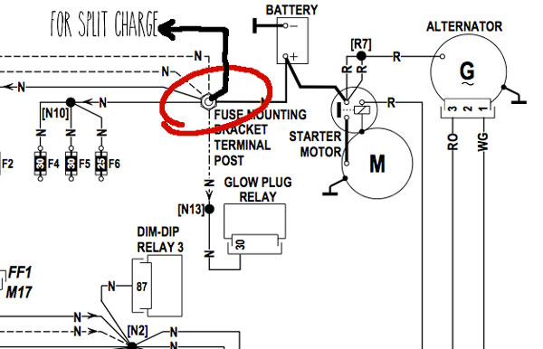
The traditional method for split charging is to take a wire from the ignition to energise a relay when the engine is running. The relay will then switch in the alternator feed to the leisure battery to let it charge just like the vehicle starter battery.
The other (and much easier) method is to use a Volt sensing circuit which detects a rise in voltage (when engine running) and energises the coil of a split charge relay to charge the leisure battery. There are many products that do this all in one package but by far the cheapest is the smartcom relay and it works very well!

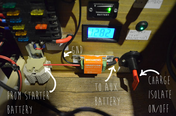

Observations (regarding split charge relay)
It can take a few seconds for the smartcom to de-engergise after the engine has turned off because the start battery Voltage takes a while to settle back down to its quiescent Voltage. Before adjusting mine it took about 2 minutes to turn off.
It would probably be best to set this up on an adjustable power supply to get a better idea of the exact switch on/off Voltage.
The components do not look very heavy duty but it should be OK for me since this is only my backup charging setup. For a permanent charging circuit I’d go for a much more heavy duty option such as the Durite Voltage sensing relay